
Rope damage diagnostic testing apparatus
Inventor’s Corner
Pat. 10,801,999 U.S. class 1/1 Int. class G01N 29/24
Inventor: Toyohiro Noguchi, Chiyoda-ku, JP., Jin Inoue, Chiyoda-ku, JP., Keita Mochizuki, Chiyoda-ku, JP., Akihide Shiratsuki, Chiyoda-ku, JP.
Assignee: Mitsubishi Electric Corp., Chiyoda-ku, JP.
In a rope damage diagnostic testing apparatus, an ultrasound applicator generates ultrasonic waves in a wire rope by making the wire rope vibrate due to magnetostriction effect. A detecting element detects changes in a state of propagation of the ultrasonic waves in the wire rope. An excitation coil and the detecting element are disposed in a parallelogram that has as a first opposite side length a length of a portion of the wire rope in which one of the outer layer strands makes one revolution around the wire rope, and that has as a second opposite side length a product of a diameter and number of the outer layer wires that are included in one of the outer layer strands.
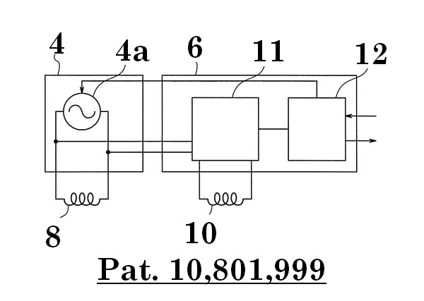
Figure 14 is an oblique projection that shows a rope damage diagnostic testing apparatus according to Embodiment 1 of the present invention, and figure 15 is a circuit diagram for the rope damage diagnostic testing apparatus in figure 14. In the figures, a housing 1 of a rope damage diagnostic testing apparatus is disposed so as to face a longitudinal portion of a wire rope 2. During testing of the wire rope 2, the wire rope 2 is moved relative to the housing 1. In figure 14, the housing 1 is represented transparently.
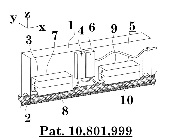
An ultrasound applicator 3, an excitation source 4, a detector 5, and a signal processing unit 6 are accommodated inside the housing 1. The ultrasound applicator 3 has an application magnet 7 and an excitation coil 8. The application magnet 7 is constituted by a permanent magnet, and applies a direct current magnetic field to the wire rope 2, which constitutes a magnetic body. The excitation coil 8 applies an alternating-current magnetic field to the wire rope 2, and makes induced currents (eddy currents, alternating currents) flow in a circumferential direction of the wire rope 2.
The ultrasound applicator 3 makes the wire rope 2 vibrate axially by magnetostriction effect, generating ultrasonic waves in the wire rope 2. The ultrasonic waves that are generated in the wire rope 2 propagate axially through the wire rope 2 along a helical structure of wires. If damage, i.e., wire breakage, is present in the wire rope 2, then the ultrasonic waves are reflected at the position of damage, or attenuate significantly. The excitation source 4 is connected to the excitation coil 8, and has a radio-frequency source 4a that generates radio-frequency electric current in a kHz through MHz range.
The detector 5 is disposed so as to be spaced apart from the ultrasound applicator 3 in the longitudinal direction of the wire rope 2. The detector 5 has: a detection magnet 9; and a detecting coil 10 that functions as a detecting element. The detection magnet 9 is constituted by a permanent magnet, and applies a direct current magnetic field to the wire rope 2. The detecting coil 10 detects the ultrasonic waves that propagate through the wire rope 2 as an alternating-current voltage. The detecting coil 10 thereby detects changes in the state of propagation of the ultrasonic waves in the wire rope 2.
The signal processing unit 6 has a waveform determining circuit 11 and a control communications circuit 12. The waveform determining circuit 11 detects the presence or absence of wire breakage in the wire rope 2 from a radio-frequency electric current waveform and the detection voltage waveform in the detecting coil 10. The control communications circuit 12 controls the radio-frequency source 4a and the waveform determining circuit 11. The control communications circuit 12 also transmits measurement results, i.e., information concerning the presence or absence of wire breakage to an external computer. In addition, the control communications circuit 12 receives signals from the external computer such as operation settings, i.e., commencement and termination of measurement, frequency and amplitude of the radio-frequency source 4a, and criteria for wire breakage, etc.
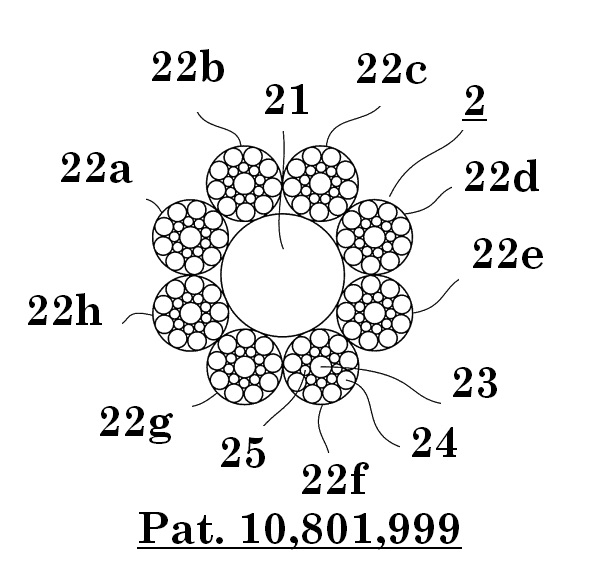
Figure 16 is a cross section of the wire rope 2 from figure 14, and shows a cross section that is perpendicular to a longitudinal direction. The wire rope 2 has: a core rope 21 that is disposed centrally; and a plurality of outer layer strands 22a through 22h that are twisted together around an outer circumference of the core rope 21. In this example, eight outer layer strands 22a through 22h are used. A cross-sectional construction of the core rope 21 is omitted in figure 16, but various constructions can be applied thereto.
Each of the outer layer strands 22a through 22h is a stranded wire that has: a steel central wire 23; nine steel outer layer wires 24 that are disposed on an outer circumference; and nine steel intermediate wires 25 that are disposed between the central wire 23 and the outer layer wires 24. A diameter of the intermediate wires 25 is smaller than a diameter of the central wire 23 and a diameter of the outer layer wires 24. In elevator wire ropes 2, breakage of the outer layer wires 24 of the outer layer strands 22a through 22h at portions that contact sheaves, called “crown breakage”, and breakage of the outer layer wires 24 at portions that contact adjacent outer layer strands 22a through 22h, called “valley breakage”, may occur.