Inventor’s Corner Patent on the method of motion compensation with synthetic rope

Pat. 10,926,981 U.S. class 1/1 Int. class B66D 1/52
Inventor: Benton Frederick Baugh, Houston, TX.
Assignee: Reel Power Licensing Corp., Oklahoma City, OK.
This patent presents a method of providing motion compensation of a subsea package with a synthetic rope comprising attaching the synthetic rope to the subsea package, supporting a first gripper with a wire rope from a winch capable of motion compensation control characteristics and gripping the synthetic rope with the first gripper, supporting a second gripper with a second wire rope, and repeating the following sequence: lowering the first gripper, the synthetic rope, and the subsea package a first distance, gripping the synthetic rope with the second gripper, releasing the first gripper from the synthetic rope, raising the first gripper the first distance, gripping the synthetic rope with the first gripper, releasing the second gripper from the synthetic rope, such that when the subsea package is lowered proximate the subsea landing location the winch capable of operating with motion compensation characteristics can operate to compensate for the vessel motion and smoothly lower the subsea package to the subsea landing location.
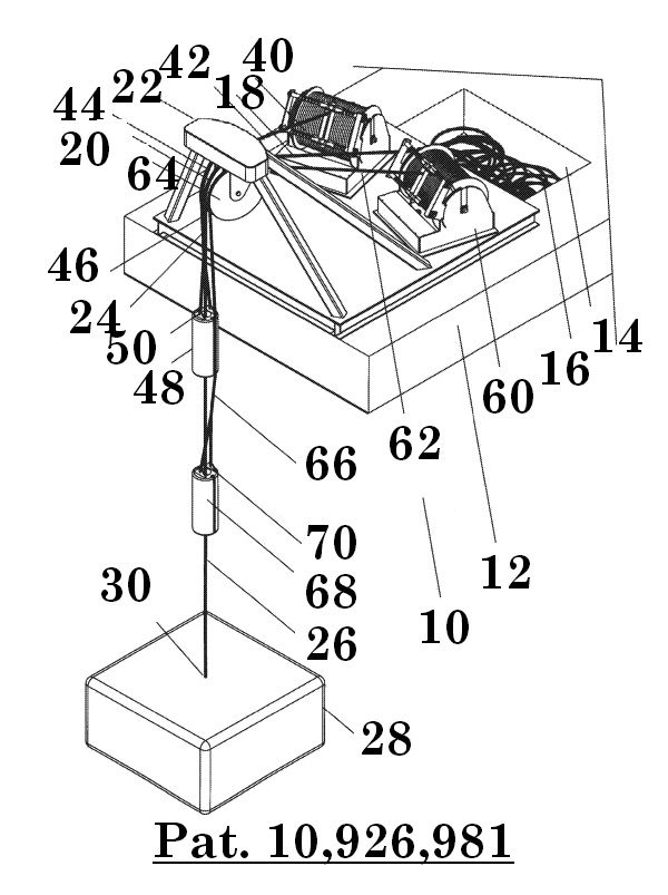
Referring now to figure 12, a pictorial view of a motion compensation system 10 is shown being landed on a boat 12 having a storage area 14 for storing a length of synthetic rope 16. The synthetic rope 16 can also be stored on a reel if desired. The synthetic rope 16 is shown coming out of the storage bin at 18, going over a sheave 20 which is supported in a mast 22, continues downwardly at 24 and 26, and connects to subsea package 28 at connection 30. An upper winch 40 is provided with a wire rope 42 going over sheave 44, with the wire rope continuing downwardly at 46 and connects to gripper 48 at connection 50. A lower winch 60 is provided with a wire rope 62 going over sheave 64, with the wire rope continuing downwardly at 66 and connects to gripper 68 at connection 70.
As is illustrated, the synthetic rope 16 passes over the sheave 20 with no significant loading, but rather the load of the synthetic rope 16 and the subsea package 28 is carried by either gripper 48 or 68. Gripper 48 and 68 have steel cables which will carry the load over sheaves 44 and 64 respectively. As will be discussed, steel cables can be utilized to pass repeatedly over the sheave with minimal heat build-up and can be wrapped onto the winches tightly to support the loadings. Synthetic rope will generate both substantial and damaging heat if run over a synthetic rope winch and cannot be wrapped tightly on a conventional winch as the outer layers will “knife” in between the inner layers.
Winch 40 lowers its gripper 48 a distance and stops, presume for example fifty feet. The winch 60 will have raised its gripper 68 fifty feet. At that time gripper 68 is engaged with the synthetic rope 16 and then gripper 48 is released. Gripper 68 is now lowered fifty feet and gripper 48 is raised fifty feet. The “hand over hand” process is continued with the subsea package 28 being lowered one hundred feet each cycle. This means that the subsea package 28 can be lowered ten thousand feet to the seafloor with two steel cable winches which have a working length of not much more than fifty feet.
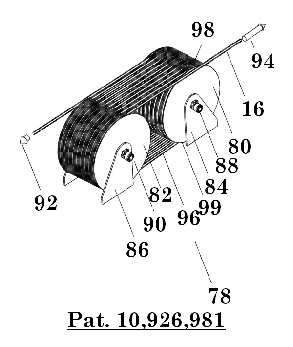
Referring now to figure 13, a conventional synthetic rope winch 78 is illustrated with synthetic rope 16 wrapped around two sheave groupings 80 and 82 which are mounted on support stands 84 and 86 and are powered by motors 88 and 90. The Sheaves of sheave groupings 80 and 82 are on a common axle (now seen) and therefore all turn the same speed. Each of the sheave groupings illustrated have ten sheaves.
The tension on synthetic rope 16 is indicated as a small load at 92 and as a high load at 94 after passing over the twenty sheaves. This means that the motors 88 and 90 have powered the sheave groupings 80 and 82 respectively and the friction between the synthetic rope 16 and the sheaves has caused a tension to be pulled. If we presume the tension at 92 is effectively zero and the tension at 90 is one hundred thousand pounds, it means on average each sheave has increased the tension of the synthetic rope by five thousand pounds. As synthetic rope is relatively elastic (has a relatively lower spring coefficient), each time five thousand pounds is added to it, the synthetic rope stretches a little more. There are twenty sections of rope 96 between the sheave groupings 80 and 82, each of which is under a different tension. This means that as the synthetic rope begins contact with a sheave such as at 98 until it loses contact with the sheave such as at 99, the tension changes. As the tension changes in the elastic synthetic rope, the length changes. If at any point the synthetic rope is travelling at exactly the same speed as the contact surface on the sheave, it will be travelling at a different speed at all other locations. This means that sliding friction is generated around most of the contact surfaces. If you can imagine that at only one point on one sheave the tension is correct for the synthetic rope to be travelling at the same speed as the surface of the sheaves, then at all other points on all the other nineteen sheaves the speed will not be matched. At all other contact points sliding will be continuously occurring, with the resulting friction heat generation.
You can imagine that with all this sliding going on with high loads, i.e. one million pounds, a lot of heat generation is occurring. When you are doing motion compensation, which means you are going back and forth over the same section of synthetic rope, this generated heat has the potential of building up to the point of damaging the synthetic rope.
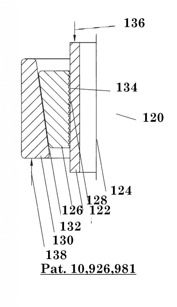
Referring now to figure 14, the difficulty of supporting the synthetic rope with a gripper such as indicated at 48 or 68. The synthetic rope is relatively slippery and is difficult to grip. If it is simply gripped, there is a chance that the grip will slip sooner or later and the rope and subsea package will be lost. It is prudent that a “failsafe” grip will be provided. Failsafe generally means that the higher the load, the higher the gripping force. Conventional failsafe slips for pipe 120 are shown with a steel pipe section 122 about centerline 124, slip segments 126 with sharp teeth 128, and bowl 130. The coefficient of friction 132 between the bowl 130 and the slip segments 126 is in the range of 0.10. The sharp teeth 128 literally bite into the pipe so exact coefficient of friction 134 is questionable, however, it is conventional to use 0.5 as the coefficient of friction to calculate with. This means that when a load 136 is imposed on the pipe and is resisted by a foundation support 138, the slip segments 126 will slip at 132 rather than 134, meaning it wedges more tightly when the load increases —it has “failsafe” support.
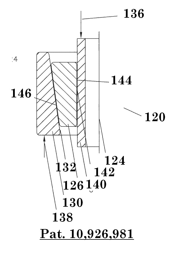
Referring now to figure 15, it can be seen what happens if the sharp teeth are removed from the slip segments so that they do not cut and damage the synthetic rope. Slip segments 140 have a smooth surface 142 which would have a comparable coefficient of friction 144 of 0.10, or even less as the synthetic rope is slicker than the steel pipe 140 shown. At this point there would be at least a fifty percent chance that the pipe will slip rather than the slip segment sliding down the bowl taper to a tighter grip. The eight degree surface 146 between the slip segments 126 and the bowl 130 add a vertical component resisting slip segment movement, insuring that the pipe will slide in the slips rather than the slip segments sliding down with a tighter grip.