Inventor’s Corner
Hoist drum and fiber rope drive having such a hoist drum
Pat. 10,807,841 U.S. class 1/1 Int. class B66D 1/34
Inventor: Ilaka Mupende, Neu-Ulm, DE., Norbert Hausladen, Biberach, DE., Steven Kreyssig, Hochdorf, DE., Nikolaj Horst, Ehingen, DE., Horst Zerza, Biberach, DE.
Assignee: Liebherr-Components Biberach GMBH, Biberach an der Riss, AT.
This patent presents a hoist drum for a fiber rope drive for high-strength fiber ropes such as crane hoists, boom adjustment or trolley traveling gear, and the like, comprising a drum body for winding up the fiber rope, guard plates encompassing the drum body, and a rope end fastening apparatus for fastening a rope end to the hoist drum. The rope end fastening apparatus of the hoist drum comprises two strand guiding passages that are disposed next to one another and that lead to a rope deflection element at which the rope end can be turned around and back so that one respective rope strand comes to lie in the two strand guiding passages; and furthermore comprises a clamping apparatus associated with the strand guiding passages for clamping at least the rope strand that is turned back around the rope deflection element in the strand guiding passage associated with the rope strand.
The hoist drums 1 shown in the figures each comprise a cylindrical drum jacket body 2 to whose axial ends respective guard plates 3 are connected which, in rough terms, extend perpendicular to the longitudinal drum axis and project radially outwardly from the drum jacket surface and have a much larger diameter than the drum jacket.
The hoist drum 1 shown can in this respect in particular be used in the hoisting gear of a crane such as a revolving tower crane or a mobile telescopic crane or a boom mast adjustment gear, but also in other hoist winches. Said guard plates 3 can be connected in different manners to the drum jacket body 2. For example, a single-piece production is conceivable, with advantageously, however, the guard plates 3 being able to be subsequently joined to the drum jacket body 2. As figure 17, for example shows, the guard plates 3 can be placed onto the drum jacket body 2 at the front side and can be fastened by fastening means in the form of bolts 5. The drum jacket body 2 can be provided with grooving 4 whose rope grooves 6 can extend over the total drum jacket body 2.
To fasten the rope end 7 of the rope 8 to be wound onto the drum jacket body 2 to the hoist drum 1, the rope end 7 of the rope 8 can be led through the guard plate 3 onto an outer side of one of the guard plates 3 and can be fastened there by means of a rope fastening apparatus 9. As figures 18 and 19 show, the guard plate 3 can have a rope leadthrough 10 in the form of a cut-out in the guard plate 3, in particular in the form of a passage hole, in a section adjacent to the drum jacket body 2.
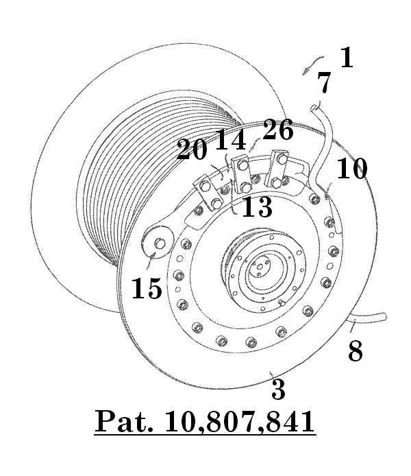
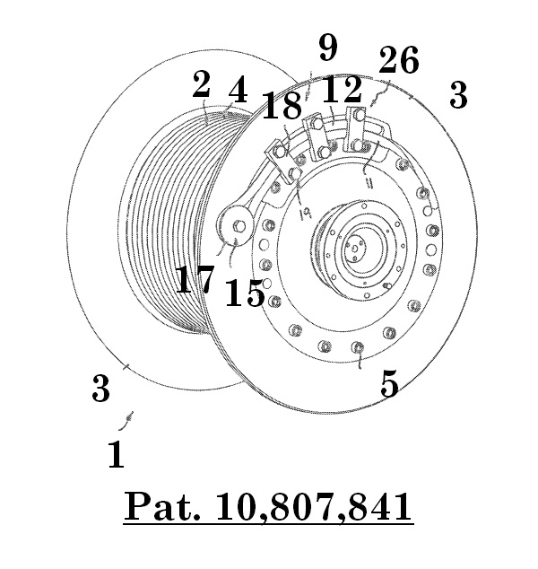
Figure 18: Schematic, perspective representation of the hoist drum that shows the threading of the fiber rope through the guard plate. 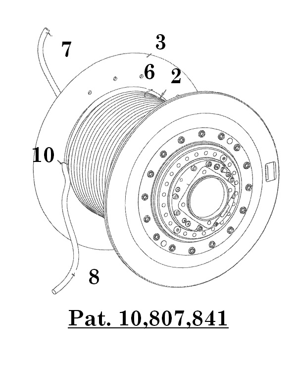
Figure 19: perspective, schematic representation of the hoist drum that shows the threading of the rope through the guard plate from the drum side.
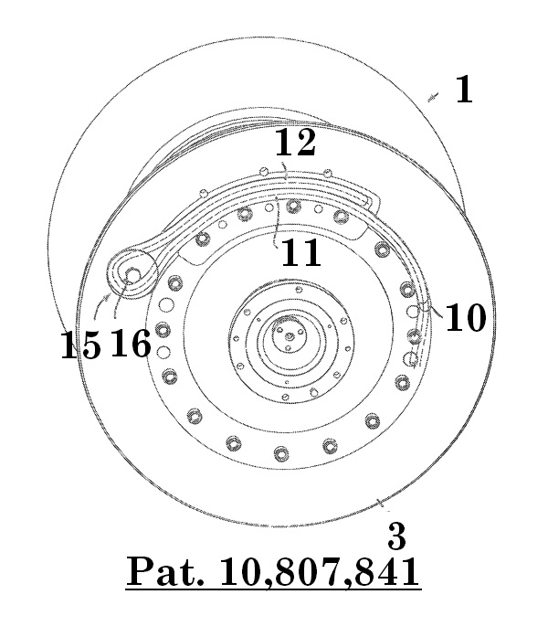
The rope fastening apparatus 9 that is provided and fastened at the outer side of the guard plate 3 can form a pre-assembled installation separate from the guard plate 3 and can be installed as a whole onto the guard plate outer side. Alternatively, the components of the rope fastening apparatus 9 can, however, also be installed separately at the guard plate 3.
As figures 17-20 show, the rope fastening apparatus 9 is configured such that the rope 8 can be clamped tight to the outer side of the guard plate 3 without a spliced rope eye and also without a pressed on rope thickening end or other rope changes, with the rope fastening apparatus 9 providing a turning back or turning around of the rope end 7 so that two rope strands 11 and 12 that are formed by different sections of the rope 8 come to lie next to one another, cf. figure 20. The rope fastening apparatus 9 for this purpose comprises two rope guiding passages 13, 14 that are disposed next to one another, that extend next to one another away from the aforesaid rope leadthrough 10 in arcuate form about the axis of rotation of the hoist drum 1 and that lead to a rope deflection element 15 of the rope fastening apparatus 9 about which the rope 8 can be turned.