Crane Patent in Inventor’s Corner

Pat. 10,836,612 U.S. class 1/1 Int. class B66C 13/20
Inventor: Naotaka Masuda, Lauf a.d. Pegnitz, DE., Kenji Urushihara, Kagawa, JP., Takashi Kawano, Kagawa, JP.
Assignee: Tadano Ltd., Kagawa, JP.
The present invention is provided with: a manipulation unit; a winch device that operates with an actuation mode of either a high speed mode or a low speed mode, and winds in or reels out a wire rope; a selection unit for an operator to select either the high speed mode or the low speed mode; a load calculation unit calculating a suspended load; a tension calculation unit calculating the tension of the wire rope; and a control unit controlling the actuation of the winch device. If the mode selected by the selection unit is the high speed mode, the manipulation unit is manipulated from a neutral state to a non-neutral state, and the suspended load is smaller than a load threshold and the tension is smaller than a tension threshold, the control unit controls the winch device so as to operate in the high speed mode.
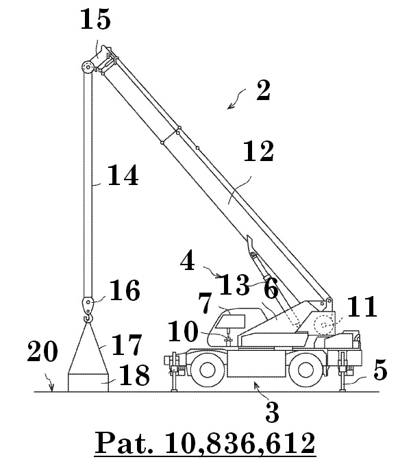
Figure 1 illustrates a rough terrain crane 2 according to an embodiment of the present invention. The rough terrain crane 2 has a winch system 1. The rough terrain crane 2 includes a vehicle section 3 and a swivel section 4 which is rotatably mounted on the vehicle section 3. The vehicle section 3 is provided with an outrigger 5. The rough terrain crane 2 illustrated in figure 1 has the outrigger 5 that overhangs. A cab 7 is mounted on a swivel frame 6 of the swivel section 4. In the cab 7, a manipulation lever 10 of the winch system 1 is arranged. A winch 11 is arranged on the swivel frame 6. A telescoping boom 12 is pivotally attached to the swivel frame 6 so as to be freely raised and lowered. A derricking cylinder 13 is arranged between the telescoping boom 12 and the swivel frame 6. The rough terrain crane 2 illustrated in figure 1 is in a crane operation posture in which the telescoping boom 12 is extended after the telescoping boom 12 is raised by the derricking cylinder 13. As illustrated in figure 1, a wire rope 14 reeled out from the winch 11 is hung around a distal end portion 15 of the telescoping boom and a hook 16. A sling wire rope 14 for suspending a suspended load 18 is hung on the hook 16. The rough terrain crane 2 illustrated in figure 1 is in a state immediately before lifting off the ground in which the suspended load 18 is grounded on a ground 20.
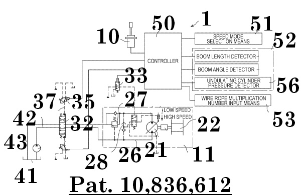
Figure 2 is a hydraulic circuit forming the winch system 1 of the rough terrain crane 2 and a control block diagram according to the embodiment of the present invention. The winch 11 has a high/low speed hydraulic motor 21 capable of driving a winch drum 22 to rotate forwardly and reversely via a speed reducer 23. The high/low speed hydraulic motor 21 can switch a displacement required for one rotation between large and small to switch a rotational speed with respect to a supply flow rate to one of a high speed mode and a low speed mode. When the high/low speed hydraulic motor 21 is in the high speed mode, an actuation mode of the winch 11 is a high speed mode. On the other hand, when the high/low speed hydraulic motor 21 is in the low speed mode, the actuation mode of the winch 11 is a low speed mode. The motor displacement of the high/low speed hydraulic motor 21 is always biased to the large displacement side. The motor displacement is controlled to be switched between large and small by a control cylinder 24.
The high/low speed hydraulic motor 21 is connected with an oil passage 25 on a hoisting side and an oil passage 26 on a lowering side. A counter balance valve 27 is provided in the oil passage 25 on the hoisting side. A shuttle valve 28 is provided between the oil passage 25 on the hoisting side and the oil passage 26 on the lowering side. The shuttle valve 28 and the control cylinder 24 communicate with each other by an oil passage 31 via a pilot switching valve 30. The shuttle valve 28 picks up a motor operating pressure generated in the oil passage 25 on the hoisting side or the oil passage 26 on the lowering side and transmits the motor operating pressure to the pilot switching valve 30. The pilot switching valve 30 switches between communication and interruption of the motor operating pressure to the control cylinder 24.
The pilot switching valve 30 communicates with an electromagnetic switching valve 33 by an oil passage 34. When a pilot pressure is sent from the electromagnetic switching valve 33 to the pilot switching valve 30 via the oil passage 34, the pilot switching valve 30 switches to the communication side. The pilot switching valve 30 and the electromagnetic switching valve 33 constitute a high/low speed switching valve. When the motor operating pressure is communicated from the pilot switching valve 30 to the control cylinder 24 (when hydraulic oil is supplied), the high/low speed hydraulic motor 21 is switched to the small displacement side corresponding to the high speed side. On the other hand, when the supply of hydraulic oil from the pilot switching valve 30 to the control cylinder 24 is interrupted, the high/low speed hydraulic motor 21 is switched to the large displacement side corresponding to the low speed side.
The oil passage 25 on the hoisting side and the oil passage 26 on the lowering side communicate with a pilot switching valve 32 that controls a direction and a flow rate of the pressure oil supplied to the winch 11. The pilot switching valve 32 communicates with a proportional solenoid valve 35 on the hoisting side by an oil passage 37. The pilot switching valve 32 communicates with a proportional solenoid valve 36 on the lowering side by an oil passage 38. The pilot switching valve 32 and a hydraulic pump 40 communicate with each other by an oil passage 42 on a pump side. The pilot switching valve 32 and the oil tank 41 communicate with each other by an oil passage 43 on a returning side. A switching direction and a switching amount of the pilot switching valve 32 are controlled by the proportional solenoid valve 35 and the proportional solenoid valve 36.
As illustrated in figure 2, a controller 50 communicates with the manipulation lever 10, a speed mode selection means 51, a load detection means 52, and a wire rope multiplier input means 53 by signal lines, respectively. Specifically, the load detection means 52 includes a boom length detector 54, a boom angle detector 55, and a derricking cylinder pressure detector 56 which are known in the art. In addition, the controller 50 communicates with the high/low speed electromagnetic switching valve 33, the hoisting-side proportional solenoid valve 35, and the lowering-side proportional solenoid valve 36 by signal lines, respectively.
The manipulation lever 10 is arranged in the cab (see figure 1), and energization to any valve between the proportional solenoid valve 35 on the hoisting side and the proportional solenoid valve 36 on the lowering side is selected depending on a switching direction of the manipulation lever 10. Further, an intensity level of a signal sent to the proportional solenoid valves 35 and 36 changes in response to the manipulation amount of the manipulation lever 10. The manipulation lever 10 corresponds to an example of a manipulation unit.
The speed mode selection means 51 is arranged in the cab (see figure 1). An operator in the cab can select either the high speed side or the low speed side by the speed mode selection means 51. The speed mode selection means 51 corresponds to an example of a selection unit.
The wire rope multiplier input means 53 is arranged in the cab (see figure 1). The operator in the cab can manually input a recognized multiplier from the wire rope multiplier input means 53. Note that the wire rope multiplier input means 53 may be configured such that a wire rope multiplier detector is arranged at the distal end portion 15 of the telescoping boom to automatically input the wire rope multiplier.