
Compact Winch
Published in the Inventor’s Corner column of Wire Rope News & Sling Technology Feb. 2021 issue
Pat. 10,889,475 U.S. class 1/1 Int. class B65D 1/14
Inventor: James A. Haley, Woods Hole, MA., Joshua A. Eaton, Woods Hole, MA.
Assignee: Woods Hole Oceanographic Institution, Woods Hole, MA.
This patent presents a lightweight winch suitable for industrial applications. It has the motor assembly self-centered with a housing within the winch drum where it may be easily accessed and removed from the winch drum. The winch drum is supported by a bearing means capable of bearing heavy loads in addition to contributing to a compact profile of the winch. The winch comprises an improved, non-load bearing levelwind mechanism for evenly winding cable about the winch drum.
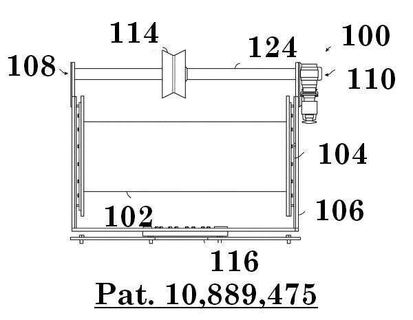
The present invention describes a lightweight, industrial winch design for use in a plurality of configurations and applications, particularly in the marine environment. While the winch 100 may be used in any suitable capacity, overall, the winch 100 is capable of hauling and supporting a heavy load on a cable such as a vehicle (e.g., an autonomous underwater vehicle (AUV), a remotely operated vehicle (ROV), a human occupied vehicle (HOV), a glider, or the like), a crate, a scientific instrument, deck equipment, moorings, or any other loads which require or may benefit from mechanical lifting, deploying, or supporting. As illustrated in figure 17, the winch 100 described herein provides a compact design which involves a motor assembly 130 disposed evenly within the internal space of the winch drum 102 by a housing 128 connected to and centered by the winch base 106 of the winch 100. Coupled to the winch drum 102 is a narrow profile bearing means 104 which reduces the side clearance of the overall system while providing a reliable, smooth rotation about the longitudinal axis of the drum and managing the heavy torque cabled load. The bearing means 104 is secured to a fixed winch base 106 designed to support the winch drum 102 and other internal elements using an amount of material for reduced weight and size considerations.
The winch 100 comprises a motor assembly 130 residing within the housing 128 which disengagably (e.g., removably) slides into an axial end of the winch drum 102. The removable installation of the motor assembly 130 is aided, in some embodiments, by the self-centering feature of the compact housing 128, as shown in figure 17. Another particular feature of this assembly method is the ease of accessibility to the motor assembly 130 for replacement or maintenance, an ability which is often made difficult by the bulky frame or inconvenient access points of conventional winches. The motor assembly 130 may be removed or at least easily accessed by one side end of the stationary housing 128, as illustrated in the side view of figure 17.
As the depicted embodiment of the present invention uses a winch drum 102 open (i.e., unsealed) on at least one axial end, passive air is allowed to flow through and around the motor assembly 130 to dissipate heat without hindering access to the motor assembly 130 or requiring added cooling components. In additional embodiments, the winch drum 102 is open on one end, while in alternate embodiments it is open on both ends. In yet alternate embodiments, the winch drum 102 has apertures to allow air to pass into it. Furthermore, centering the motor assembly 130 via a housing 128 within the winch drum 102 allows more surface area of the motor assembly 130 to be air-cooled.
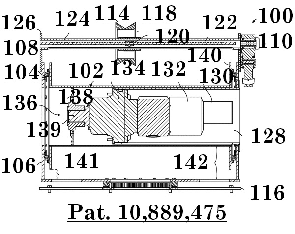
As shown in figure 17, the integration of the motor assembly 130 reduces the overall height profile of the winch 100 unit as compared to a conventional winch which typically disposes its motor assembly in a case adjacent to, or at a raised position around, the winch drum 102. Moreover, the integration of the motor assembly 130 into the winch drum 102 frees additional area above and around the winch drum 102 to permit the rearrangement of the levelwind mechanism 108. The reduction in height clearance also allows the winch 100 to fit and operate within areas of lower clearance previously inaccessible to conventional winch models.
The overall footprint of the winch 100 is also substantially reduced by the new design, which further expands the possible attachment or operation positions of the winch. This decrease in footprint will have immediate impact in numerous fields of use such as the marine environment where space on a vessel is limited. Conventional winches routinely require large and bulky frames to secure the winch, the motor assembly, and the plurality of other components. The inventive winch 100, as illustrated in figure 18, is largely defined by the size of the winch drum 102 when the winch 100 is mounted directly onto a platform by the winch base 106. In various embodiments such as the one as shown in figure 17, the winch 100 may also be utilized with a low profile turntable 116 or other suitable mounting base as would be readily identified by one having ordinary skill in the art in light of this disclosure, which redefines the footprint of the winch 100 to the size of the turntable 116. Even in such embodiments, the winch 100 still consumes less deck space for operation than conventional winch constructions and may also be rotationally adjusted.
The side clearances of the inventive winch 100 is also condensed by replacing the conventional pillow blocks typically used in winch constructions for rotation with a slimmer bearing means 104, which in preferred embodiments are lightweight rolling element bearings (e.g., slewing bearings) with the strength capacity and force resistance equal or greater than heavy pillow block bearings or similar mountings.
The overall size reduction adds additional advantages which can be seen in various embodiments including lighter weight, easier transportation, simpler installation, and/or cost-effective fabrication. In at least one embodiment, the winch 100 requires no additional housing or framing; however, the winch 100 may be integrated into an existing housing or frame to mount to a desired position on a platform. In many cases, the winch 100 may be easily manually adjusted due to the reduction in weight and/or size.
The winch 100 also includes an improved lightweight levelwind mechanism 108 which further reduces the winch’s 100 size clearance and weight. Conventional winch constructions spool the cable through the levelwind mechanism 108 disposed at a frontal position level with the winch drum 102. At this position, the levelwind must bear the weight and torque of the cabled load which most often requires a high strength double beam design. One or more embodiments of the inventive winch 100 reduces the levelwind mechanism 108 to a single lightweight beam 112 arranged above the winch drum 102 to remove any substantial torque forces from bearing upon the levelwind mechanism 108 during operation. Alternate embodiments may move the single lightweight beam 112 to other suitable non-load bearing positions. The levelwind motor assembly 110 is often mounted to the winch base 106 keeping the profile of the winch 100 as compact as possible.
As previously mentioned, the motor assembly 130 may be easily accessed and disengaged from the winch drum 102 via the quick removal means. As various vehicles or loads may be deployed and retrieved with a winch, it is common to have more than one size or type of winch available on site in order to manage all of the loading demands. One feature provided by various embodiments of the inventive model is the ability to utilize a plurality of cables or ropes of various type, length, and/or gauge (e.g., diameter), including synthetic rope, which may be exchanged with the inventive winch 100 to suit a specific load. Likewise, it is an object of at least one embodiment of this invention to provide a winch wherein the winch drum and/or motor assembly may be timely exchanged to one of suitable abilities for the task at hand and limit the individual winches required.
As shown in figures 17 and 18, the motor assembly 130 is disposed within the winch drum 102, wherein the motor assembly 130 engages a drive means 136 to translate the power generated from the motor 132 into rotational force, driving the forward or reverse turning motion of the winch drum 102 during operation. At one end, the drive means 136 engages the motor assembly 130 while at the other end the drive means 136 is attached to the drum engagement means 138. The drum engagement means 138 connects to a portion of the winch drum 102 to provide drum rotation.
Rotation of the winch drum 102 is further facilitated by the bearing means 104 which is generally disposed on one or both adjacent axial ends of the winch drum 102. The winch drum 102 is attached to the rotatable inner surface of the bearing means 104, while the fixed outer surface of the bearing means 104 connects to the winch base 106 (which comprises the winch frame and drum mount). In some instances, the winch base 106 is directly mounted to the platform but is often attached to a turntable 116 which is attached to the platform.
The system comprises additional components such as the levelwind mechanism 108 which is attached to the winch base 106 and in contact with the cable being wound about the winch drum 102. The levelwind mechanism 108 is powered by the levelwind motor assembly 110 to drive rotation of the lead screw 122 and screw nut 120 which is attached to the carriage 118 engaged with the sheave 114. The cable wound about the winch drum 102 passes over the sheave 114 to connect to the vehicle, heavy load, or other rigging for deployment/retrieval. Another advantageous aspect of the present embodiment is the redesigned portable controller to provide remote operation around the platform. The motor assembly 130 is connected to a power source and is regulated by the controller. The controller may plug into a suitable terminal wherein the terminal is appropriately connected to the motor assembly 130 to signal control of motor speed and rotation direction.