
Inventor’s Corner
Adjustable Suspension Assembly
Pat. 11,002,026 U.S. class 1/1 Int. class E04G 3/30
Inventor: Paul Apostolopoulos, Clarence, NY., Davy E. Passucci, Clarence Center, NY.
Assignee: Paul Kristen, Inc., Tonawanda, NY.
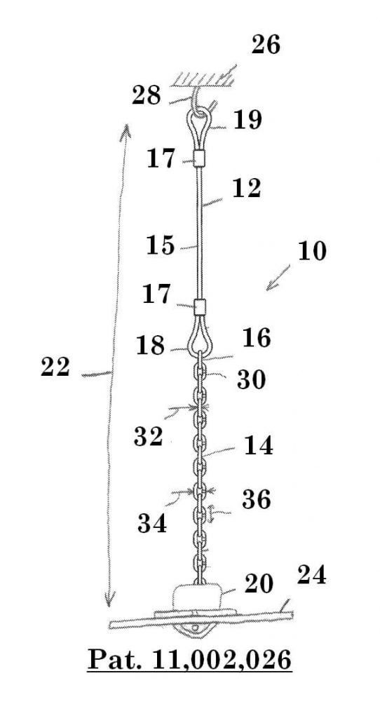
Figure 16: Side view, partly schematic, of an adjustable suspension
assembly, illustrated suspending a platform from a bridge structure.
This patent presents an adjustable suspension assembly for suspending a lower structure such as a platform from an upper structure such as a portion of a bridge. A sling, which is attachable at one end to the upper structure, is attached at its other end to one end of a chain. A device, which is attachable to the lower structure, has a pair of aligned apertures in its side walls for receiving pins. The pins are spaced to receive a thickness of a chain link but not to receive a width of the link, whereby a selected link to achieve a desired lower structure height may be cinched between the pins. The other end of the sling, which comprises a cable, has an eyelet formed by folding an end portion of the cable back over the cable and swaging the cable end portion to the cable. The chain is attached to said eyelet by receiving the end portion of the cable in one of the chain links before the cable end portion is swaged to the cable.
Referring to the Illustrations in figures 16-19, there is shown generally at 10 a suspension assembly, which comprises a combination of a conventional sling 12, a chain 14 one end 16 of which is attached to an end 18 of the sling 12 and an other end of which is attached to an adjustment device, illustrated generally at 20, in a manner as described hereinafter for providing adjustability to the overall length or height, illustrated at 22, of the suspension assembly 10 for thereby providing a desired height to a platform 24 to which the adjustment device 20 is attached. Each of the parts thereof, unless otherwise specified or apparent, is composed of steel or other suitable metal or other suitable material.
The sling 12 is a length of cable 15 (or wire rope or other suitable flexible strand) having attachment means in the form of a loop or eye or eyelet 19 at each end wherein the cable 15 is folded back over and attached to itself to form an eyelet or loop, and a protective thimble (not shown) suitably received within the eyelet 19. The sling 12 shown in figure 16 is of a type which is non-adjustable, wherein, for each eyelet 19, the respective end portion of the cable 15 is looped back and attached to itself permanently by a swaged connection utilizing a swage sleeve 17 (which may come in various sizes such as, for example, a diameter of 1/2 inch) which is caused to encircle and firmly grip the respective portions of the cable 15 thereby providing a strong connection of the cable to itself thereby forming the eyelet 19. Such a swaging process for forming an eyelet of a sling is well known in the art to which the present invention pertains. The upper eyelet 19 (the eyelet opposite end 18) is connected to a bridge or other suitable structure, illustrated at 26, by a suitable attachment means such as a clip or hook, illustrated at 28, for use of the suspension assembly 10 for supporting, for example, the platform 24 from the bridge structure 26.
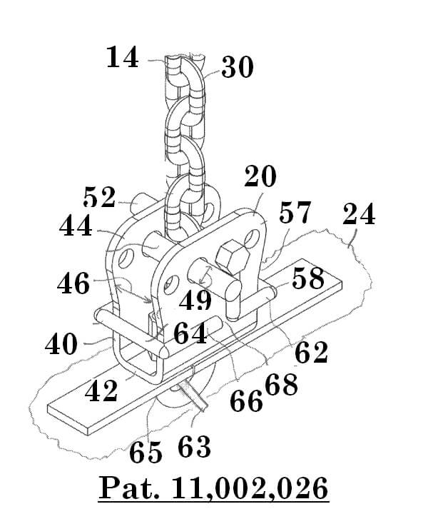
Figure 17: First enlarged perspective view of a portion of the assembly.
The chain 14 is formed of a plurality of, for example, 21 to 25 interconnected identical links 30 (as needed to provide the desired range of height adjustment), the upper end portion or link 16 (preferably the end link) of which is received on the lower end or eyelet 18 prior to the above described swaging process thereby desirably permanently and inexpensively connecting the upper end 16 of the chain to the lower end 18 of the sling 12.
Unless otherwise stated, illustrative dimensions provided herein are for exemplary purposes only and not for purposes of limitation. Each link 30 for an exemplary chain has, for example, a thickness, a width, and a height, illustrated at 32, 34, and 36 respectively, which, for a suitable chain 14, may, for example, be 3/8 inch, 11/4 inch, and 2 inches respectively, the width 34 being substantially greater than the thickness 32. The chain 14 is of a type wherein, as viewed from a particular direction such as in figure 16, alternately the thicknesses 32 and the widths 34 face in that particular direction and have very small or limited rotation ability therefrom. Thus, as viewed in figure 16 of the drawings, alternately the thicknesses 32 and the widths 34 face the viewer.
Referring to figures 17-19, the device 20 comprises a plate 40 bent or otherwise suitably formed (for example, three flat plates may be welded together to form the plate 40) to define a bottom wall 42 and two side walls 44 which extend upwardly from edges of the bottom wall 42. The spacing, illustrated at 46, between the side walls 44 is greater than the width 34 of a link to allow passage easily of the width 34 of a link there between, as illustrated in figure 17. This spacing 46 may, for example, be about 11/2 inch.
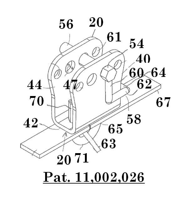
Figure 18: Second enlarged perspective view of a portion of the
assembly.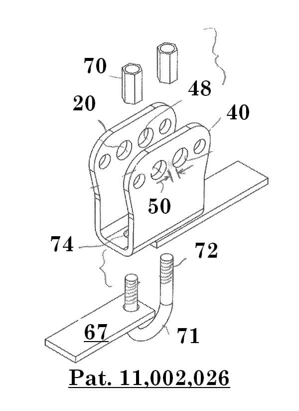
Figure 19: Blown up view of a portion of the assembly.
Each of the side walls 44 has in its upper portion a pair of spaced apertures, illustrated at 48, wherein the apertures 48 in one of the side walls 44 are aligned with the apertures 48 respectively in the other of the side walls 44. A pin 52 is insertable in each aperture 48 in one side wall 44 and the corresponding aligned aperture 48 in the other side wall 44. The pins 52, which have heads 54, are desirably inserted from opposite side walls 44 respectively, as illustrated in figure 17. The apertures 48 in each side wall 48 are spaced a distance, illustrated at 50, so that when the pins 52 are inserted in respectively aligned apertures 48, the distance between the pins 52 will be equal substantially or a little more than the thickness 32 of a link and will be substantially less than the width 34 of a link. This distance 50 may, for example, be about 5/16 inch.
While this exemplary distance 50 is less than the exemplary link thickness of 3/8 inch, this will nevertheless work because the pin diameters, illustrated at 49, are substantially less than the diameters, illustrated at 47, of apertures 48 thereby to provide plenty of play and wiggle room for receiving a link thickness between the pins and allows the distance between the pins 52 to spread to a distance, for example, 1/2 inch, which is greater than the distance 50 between the apertures and greater than the exemplary 3/8 inch link thickness for easily accommodating a link thickness.
In order to retain the pins 52 in the respective aligned apertures 48 without the necessity of applying nuts, the pins 52 are preferably scaffold pins, which may also be referred to as adjustment retainers and which are disclosed in the aforesaid U.S. Pat. No. 9,784,001. The scaffold pin includes, in addition to the shank 56 and head 54, a locking part 58 which utilizes gravity for retaining the shank 56 in the respective aligned apertures 48 as follows. The locking part 58 includes a first portion 60 which extends from the head 54 downwardly, a second portion 62 which extends from an end of the first portion 60 along side a lower portion of the respective side wall 44 to just beyond the nearest edge of the respective side wall 44, a third portion 64 which extends from the end of the second portion 62 across both side walls 44, and a fourth portion 66 which extends from the end of the third portion 54 along the respective side wall 44 to a point 68 of termination.
It can be seen in figure 17 that the fourth portions 66 restrain the pins 52 from being removed from their apertures 48 (due to impingement of the fourth portions 66 against the side walls 44 respectively). It can also be seen that, by movement of the locking parts 58 upwardly, the fourth portions 66 can be made to clear the side walls 44 respectively so that the pins 52 can then be removed from the apertures 48 respectively. The side edges of the side walls 44 are slightly curved inwardly, as seen at 57 in figure 17, to allow ease of movement of the locking parts 58 between the lower and upper positions. The force of gravity keeps the locking parts 58 in their downward positions as seen in figure 17. When force is applied to the suspension assembly 10 such as by attachment of the platform 24, the pins 52 are pinched in the respective apertures 48 thus further insuring that the pins 52 will not come out of their apertures 48 respectively. Additional apertures 61 (or at least one additional aperture 61) are provided to the sides of apertures 48 respectively to allow attachment of a lifting device for temporary lifting of the platform 24 so that the cable 14 may be attached to or detached from the device 20 or for any other suitable purpose.
The platform 24 is supported by cables 63 such as shown in, for example, the aforesaid U.S. Pat. No. 5,730,248. The decking 24 is attached to the cables 63 at multiple locations by clips 65 comprising a pair of plates 67 which abut (end edge to end edge) to cover openings (not shown) in the decking 24 and a U-bolt 71 which receives a cable 63, and nuts 70 applied to its two threaded end portions 72 thereby securing the cable 63 to the decking 24 at that point. Similar clips are also shown in the aforesaid U.S. Pat. No. 5,730,248 and in others of the aforesaid patents. For example, a clip may have a J-bolt with one end connected to a plate and the other end receiving a nut. The use of underlying cables to support decking for platforms and the attachment thereof to the decking by clips of various types is well known in the art.
In accordance with the present invention, the end portions 72 of the U-bolt are also received in apertures, illustrated at 74 (one shown), in the bottom wall 42 of the device 20 before the nuts 70 are applied, thereby attaching the device 20 to the platform 24, without the need for expensive hooks or the like. If a different type of clip is used, it may suitably attach the platform 24 to the device 20 using principles commonly known to those of ordinary skill in the art to which the present invention pertains.
In order to suspend the platform 24 at the desired height, the sling eyelet 19 (the one unattached to the chain 14) is suitably attached to an overhanging bridge portion 26 such as by receiving the eyelet on the hook 28. The device 20 as well as an underlying cable 63 are attached to the platform with the U-bolt 71 or as is otherwise suitable. Using a temporary suspension device such as another sling attached at one of the apertures 61 to maintain the platform 24 temporarily lifted, the correct chain link 30 for the desired platform height is selected and its thickness 32 inserted in position between the side walls 44 and the pins 52 inserted into the respective aligned apertures 48 (while suitably holding the locking parts 58 above the side walls 44, then allowing the locking parts to fall by gravity and urging as necessary into locking position after the pins 52 are inserted), thereby cinching the selected link 30 for the desired platform height into position.
As seen in figure 17, the adjacent links 30 cannot pass width-wise through the spacing 50 between the pins 52 thereby trapping or locking the selected link 30 at the desired height 22 and thereby providing an adjusted height to the suspension assembly 10. To remove the suspension assembly 10, the temporary suspension device is again applied at one of the apertures 61 to relieve force, the locking parts 59 are moved so that the fourth portions 66 are above the side walls 44, and the pins 52 are removed from the apertures 48 respectively and the chain 14 removed from the device 20.