
Inventor’s Corner of Wire Rope News & Sling Technology Magazine
Hoisting and Lowering Device
Pat. 10,737,919 U.S. class 1/1 Int. class B66D 3/04
Inventor: Mark Groves, Meridian, ID.
Assignee: Grid Manufacturing Corporation, Meridian, ID.
A device, system and method are used for hoisting and lowering a load. The device has a front plate that may be displaced to reveal a sheave. The device also has a friction accessory. The friction accessory is arranged to create friction between a rope and the device when a load is suspended from the device using the rope and where the device is secured to a support structure. The system may be prepared by an operator, having ascended to an elevated location, and further allows the operator to lower the load from the elevated location prior to descending.
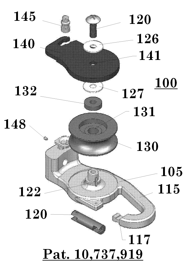
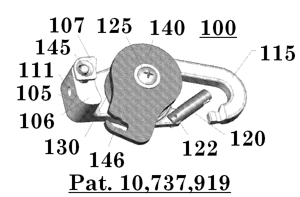
Figures 1-5 illustrate one embodiment of a device 100 for hoisting or lowering a load, comprising a pulley. The device 100 has a main body 105, a sheave 130, and a front plate 140. The pulley is held together by a bolt 125, which goes through an axial hole 141 in the front plate and through a center 131 of the sheave 130 and anchors in the main body 105. Both the front plate 140 and the sheave 130 are configured to rotate about the bolt 125. As shown in figure 1, device 100 further comprises spacers 126, 127 and 132, which allow the sheave 130 and the front plate 140 to turn. A friction accessory 115 extends from the bottom of the main body 105. A gate 120 connects a distal end 117 of the friction accessory 115 to the main body 105. The gate 120 is anchored by a pin 122 in the main body 105 and, when closed, forms an enclosed space 121 between the friction accessory 115 and the main body 105.

Figure 1: Exploded view of a device for hoisting and lowering a load. 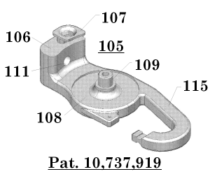
Figure 2: Drawing depicting the main body of the device for hoisting and lowering a load. 
Figure 3:. Drawing depicting a side view of the device for hoisting and lowering a load. 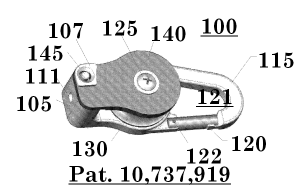
Figure 4: Drawing depicting a perspective view of the device for hoisting and lowering a load wherein the front plate is shown in closed position. 
Figure 5: Drawing depicting a perspective view of the device for hoisting and lowering a load wherein the gate is shown in closed position.

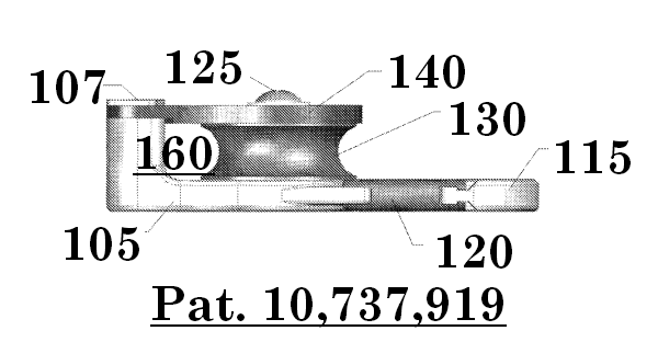

Referring to figure 2, the main body 105 of the pulley comprises a depression 108 and a hub 109 for accommodating the sheave 130 when assembled. The main body 105 further comprises a top hole 111, which accommodates a fastener 110. A front face 107 of the main body 105 is visible on the front of the device 100 when assembled and a recess 106 of the main body 105 is set back from the front of the device 100 and the front face 107 to accommodate the front plate 140. The front plate 140 is held in a closed position by releasable clasp 145, located in front face 107. The front plate 140 also comprises an opening 146 which intersects the releasable clasp 145. The device 100 further comprises a space between the sheave 130, the main body 105, the front plate 140 (when closed), forming a chamber 160 (see figure 3).
The device 100 is designed to withstand significant stresses placed upon it as a load is hoisted or lowered. In particular, the main body 105 is be configured to withstand the greatest portion of the stresses caused by the weight of the load. As seen in figure 3, where the device 100 is viewed from the left side, the main body 105 extends along a back side of the device 100, opposite front plate 140. In this example, the thickness of the main body 105 is notably thicker than the front plate 140 because the main body 105 is designed to carry a significant majority of the load. The main body 105 may be formed of steel or another structurally appropriate material, as known in the art. Further, the main body 105 may be manufactured by machining the chosen material or may be formed in a cast. Other appropriate manufacturing methods known in the art may also be used.
The friction accessory 115 is designed to create a significant amount of friction between a cord (e.g., a rope or cable) and the device 100, without causing damage to the cord. The friction accessory is attached to the main body 105 and comprises an elongated appendage which may have one or more turns or twists therein. In some embodiments, the friction accessory 115 is also connected to the main body 105 by one or more gates 120 that extend from the main body 105 and contact an end 117 of a corresponding arm when in a closed position. For example, figures 4 and 5 show the gate 120 connected to the main body 105 with the pin 122. The gate 120 is free to rotate about the pin, wherein the gate 120 is biased towards a closed position. The biasing feature of the gate 120 may result, for example, from using a spring pin as the pin 122. The present disclosure further contemplates various alternative designs of the friction accessory 115, wherein the friction accessory 115 may have a more constricting enclosed area 121. Other configurations of the friction accessory 115 may comprise the enclosed area 121 with an adjustable width, (e.g., a pinching device), such that the amount of friction resulting from the friction accessory 115 may be adjusted for a particular application.