
Manipulation Rope
Inventor’s Corner, October 2020 Issue of Wire Rope News & Sling Technology Magazine
Pat. 10,716,456 U.S. class 1/1 Int. class A61B 1/00
Inventor: Keiji Matsumoto, Ono, JP.
Assignee: TOKUSEN KOGYO CO., LTD., Ono, Hyogo, JP.
A manipulation rope having an excellent torque transmittability is provided. A manipulation rope is a rope that is advantageously used as a manipulation rope for a medical instrument, and includes a side wire or a side strand which is an outermost layer, the side wire or the side strand having a spiral shape in which a flatness that is an aspect ratio obtained by a major axis being divided by a minor axis is greater than 1.00 and not greater than 1.10. An elongation of the rope at a time when a tensile load that is 1.0% of a breaking load is applied, is preferably not less than 0.04% and preferably not greater than 0.10%.
Figures 5-7 illustrate a plurality of examples of manipulation wire ropes (hereinafter, each simply referred to also as rope) according to the present invention. Ropes 2, 8, 16 each include a strand obtained by a plurality of wires being stranded. The present invention is not limited to the structure of the embodiment shown.
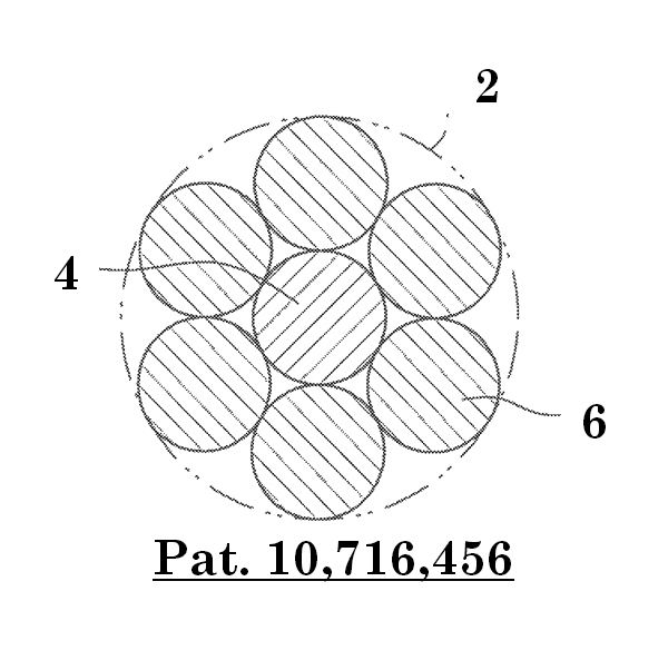
Fig 5 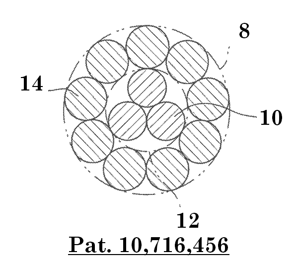
Fig 6 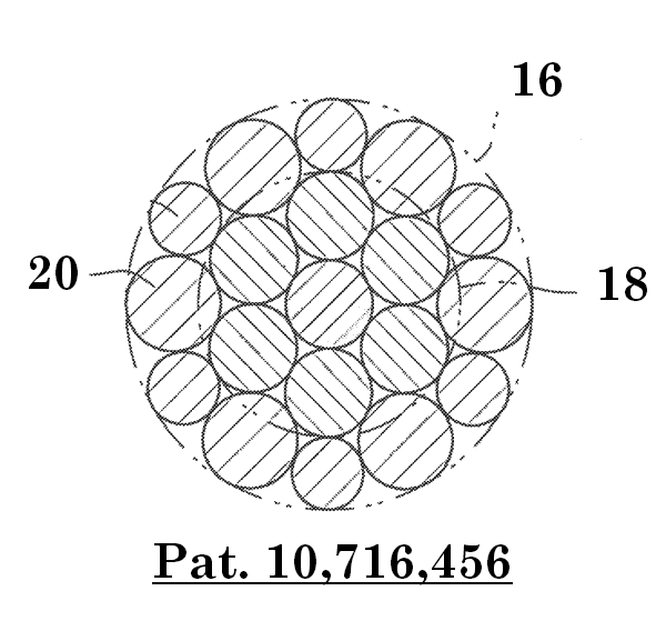
Fig 7
The rope 2 shown in figure 5 has a 1+6 layer stranded structure which includes one core wire (core) 4 and six wires (each of which is also referred to as side wire) 6 in the outermost layer. The rope 8 shown in figure 6 has a 3+9 layer stranded structure which includes a core strand 12 formed from three wires 10 and nine side wires 14. The rope 16 shown in figure 7 has a 1+6+12 layer stranded structure which includes: a core strand 18 which is a 1+6 layer stranded inner layer; and 12 side wires 20. In the rope 16, the side wires 20 have different diameters such that the transverse cross-sectional shape of the rope 16 is close to a circular shape. However, the rope 16 is not limited to one having such a structure, and all the side wires 20 may have the equal diameter. The rope 2, 8, 16 has a stranded structure suitable to a manipulation rope used for a medical instrument. However, the rope 2, 8, 16 is not limited to such a manipulation rope.
The rope 2, 8, 16 of the embodiment can be used for a medical instrument. The rope is attached to a medical instrument for manipulation such that, for example, the proximal end portion of the rope is connected to an operation unit, being held by hand, of the medical instrument, and the leading end portion of the rope is connected to a treatment unit. Torque and pushing and pulling force applied to the proximal end portion are transmitted to the leading end portion, and the treatment unit is allowed to perform a treatment operation.
In the present embodiment, the wire of the rope 2, 8, 16 is formed from an austenitic stainless steel such as SUS304 and SUS316 or the like, a nickel-titanium alloy, or the like. Needless to say, the material of the wire is not limited to such a material. The tensile strength of the material of the wire is preferably not less than 2000 MPa, more preferably not less than 2500 MPa, and particularly preferably not less than 2800 MPa. The shape of a spiral of the side wire 6, 14, 20 or the side strand which is an outermost layer is not completely circular but ellipsoidal or oval when the rope 2, 8, 16 is disassembled (disentangled). In other words, the spiral is a so-called flattened spiral.
In the side wire 6, 14, 20 or the side strand, the flatness (also referred to as aspect ratio) is preferably greater than 1.00 and preferably not greater than 1.10. The flatness represents an aspect ratio, of the above-described flattened spiral of the disentangled side wire or side strand, obtained by dividing the major axis by the minor axis. On a projector, the disentangled side wire or side strand is rotated around the center axis thereof. In this process, the diameters of the spiral are measured at any plurality of angular positions (for example, five positions). The plurality of angular positions are preferably spaced from each other at equiangular intervals. The greatest value among the plurality of measured values is determined as the major axis. The diameter of the spiral which is measured in the direction obtained by 90° phase rotation around the center axis of the side wire or the side strand being performed from the direction in which the major axis is measured, is determined as the minor axis. In the disentangled side wire or side strand, a plurality of spirals are formed continuously along the axial direction thereof. Therefore, as each diameter in the 90° intersecting direction, an average of a plurality of measured values (for example, at any 10 positions) is adopted.
When the flatness is in the above-described range, the rope becomes flexible and is easily bent. Further, friction between the side wires or between the side strands is increased, and friction between the side wire or the side strand and the core wire or the core strand is reduced, thereby reducing energy loss in transmission of rotation of the rope. By this action, transmission of rotational force from the proximal end to the leading end is facilitated, and torque transmittability is improved.
When the flatness is not greater than 1.00, friction between the side wire or the side strand and the core wire or the core strand is increased, so that energy loss in transmission of rotation of the rope may be increased. Meanwhile, when the flatness is greater than 1.10, a so-called open structure is caused, and the rope may be difficult to stably manufacture. In this viewpoint, the flatness is preferably not less than 1.01 and preferably not greater than 1.05.
An initial elongation of the rope 2, 8, 16 is preferably not less than 0.04% and preferably not greater than 0.10%. The initial elongation of the rope is obtained by an elongation (increase rate of length) of a rope at a time when a tensile load that is 1.0% of a breaking load of the rope is applied being represented as a percentage.
The rope having a great initial elongation is flexible and easily bent. That is, the rope having a great initial elongation has a small longitudinal elastic modulus (Young’s modulus). When the initial elongation is less than 0.04%, friction between the side wire or the side strand and the core wire or the core strand is increased, so that energy loss in transmission of rotation of the rope may be increased. Meanwhile, when the initial elongation is greater than 0.10%, the rope tends to have a so-called open structure, and the rope may be difficult to stably manufacture.
The initial elongation is confirmed by a tensile testing for a rope to be tested. The tensile testing can be performed in compliance with the standard of JISZ2241 (2011). Initially, a breaking load of the rope to be tested is measured. Then, the rope to be tested is attached to the tester, and a tensile load is applied thereto. At a time when the tensile load becomes 1.0% of the breaking load, increase of the gauge length that is set in the axial direction of the rope to be tested is measured. The percentage of the increase relative to the original gauge length is set as the initial elongation.
A strand angle of the side wire 6, 14, 20 or the side strand of the rope 2, 8, 16 is preferably not less than 15°. In the rope in which the strand angle is not less than 15°, the initial elongation that is not less than 0.04% can be easily obtained. The strand angle is an angle between the wire or the strand, and the center axis of the rope or the strand. In the description herein, the strand angle is an angle between the side wire or the side strand, and the center axis of the rope.
A process for manufacturing the rope will be briefly described below. Initially, each wire of the rope is adjusted in the wire drawing process step such that a required tensile strength can be obtained. Then, preforming is performed for the side wire or the side strand by a preformer in the wire stranding process step such that a required flatness can be obtained. In particular, the preforming (forming) is performed such that the spiral of the side wire or the side strand has a flattened transverse cross-section. In the heat treatment process step for the rope, not batch processing but continuous processing is performed. Specifically, the rope, to be processed, which passes through a heat treatment furnace is tensioned at an inlet and an outlet of the heat treatment furnace. Thus, the straightness of the rope is improved. Further, the flatness of the side wire or the side strand is determined.