Dangers in Crane Testing: Expect the Unexpected
by Dennis J. O’Rourke, CSP
Recent crane accidents prompted this article. I have certified cranes for various agencies and companies since the 1960s and know the requirements of the work. I find these accidents have peculiar circumstances in both causes and the number of injured and deaths (33). Couldn’t this have been prevented? Who dropped the ball?
“There but for the grace of God, go I.” When John Bradford first uttered these words, he was reacting to prisoners marching to 17th century gallows. Perhaps a bit too dramatic a statement for some, but to the people involved, they may think appropriate. In the vernacular of the street, “they were just in the wrong place at the wrong time.” Both viewpoints have merit. If it were a friend of yours that was killed, you would seek solace. But, if these accidents just cost you money, you may ask, why were they there in the first place, and who screwed up?
Myself being mercenary, ask, “Suppose these flawed cranes with their underlying defects, pass these first tests that are performed cautiously under perfect conditions and certified?” Then, one month later, working at job speeds, hectic conditions, and usual inertial load moments — failed, the person who signed that certificate would have problems.
Two accidents occurred during their initial testing and certifications “commissioning” the cranes. In the U.S. OSHA Maritime, it is Inspection and Load Testing for Initial Certification, and this inspection & testing is required every four years. After that, an inspection each year between the testing cycles unless modified.
THE TRAP
The U.S. Navy places “load-bearing components” in two categories — load-bearing and primary load-bearing. The latter are components that the stress-induced in them is directly proportional to the load on the hook and require in-depth documentation.
It’s funny; the psychology (behavior) of overload testing of a crane is taken casually by some people very familiar with cranes. Why? Simple: Most incidents with cranes are caused by weather, operator error, or rigging breakage. I heard it said, “we over-load the cranes anyway, go for it!”
Before the test, the crane undergoes an intense visual and dimensional calculation of its structure, followed by mechanical/electrical performance and operating evaluations with no loads. The testing is performed; under good weather, known loads, measured radius, professional rigging, and smooth, controlled movements. What could go wrong?
If the crane is new, to be honest, it is taken for granted that it was built correctly — and the manufacture’s engineers are always self-assured. The inspection is more straightforward, with no dirt, no wear, or repairs/modifications to evaluate. The effort is to determine that the configuration of the crane conforms with the manufacturer’s documents. The essentials are how much counterweight, type of wire rope/reeving, length of booms/jibs, accessories equipped, and capacity charts/manuals. These form a “benchmark” of documentation, referred to during future crane surveys allowing surveyors to recognize alterations that may affect the capacity or operating control of the crane.
In these accidents, the structural failure of the mechanical/structural component occurred far below the crane’s capacity. The tests are started with light loads, just warming up to build confidence in the crane’s ability to lift their capacity loads. The sequence of testing is: we perform the maximum radius first (lightest weight), followed by mid-radius and then minimum radius, which is the maximum load. The new 5,000-ton ship crane was lifting 2,600-ton when it failed. The new port crane had handled 50% of its capacity two days before and then collapsed during the test; this would have been unexpected.
What would we expect to fail when load testing? Statistically, and proven so in my experience — our failures of the hoist drive, brakes, and sheave. A careful inspection before testing generally exposes unsatisfactory conditions that are correctable before an accident.
WHAT COULD WE DO?
At the time of the initial certification inspection, the surveyor is not evaluating the material selected to construct the crane or the method of assembly. There is no “checking off” of sub-components, the design, or the material selected for the final product. What they are doing is verifying that the final product before them agrees with the manuals and drawings provided by the manufacture. A 40-ton hydraulic R.T. crane — easy. A 5,000-ton newly designed floating crane — not so easy.
The crane certifier is responsible for determining that the crane is correctly assembled, no physical deficiencies, and is functioning correctly during the overload test, not to check Engineering. All areas of the crane are not accessible for inspection. John W. Davis, PE president of the Cranes Certification Association of America (CCAA), states, “…the certificate can clearly define the scope of the inspection/testing and state the limitations involved, thereby specifying the limits of responsibility of the surveyor.” In our business it’s called “failure to warn.” (See Fig. 1).
Photographs courtesy of Dennis O’Rourke
These accidents are concerning because none of the on-site efforts could have prevented their occurrence. Then, how could they have been prevented? Could something be done at the time of these final acceptance tests? Are some things just unforeseen? Some say that everything can be prevented, in theory, but at what cost. Maybe two unusual crane accidents a year aren’t too big a price to pay — in not trying to eliminate all accidents!
Some refer to the crane companies as fabricators and designers. They depend on critical sub-assemblies from suppliers. So, vender-source inspection is vital to the overall performance of their product. For example, no crane company makes its turntable slewing ring bearing or the bolts that hold it together and securing it to the crane. None make the hook in their load blocks.
Identifying primary load-bearing problems can only be achieved at the sub-assembly or material selection levels, which means the necessary amount of quality control in the manufacturing process. Monitoring of the vendor to determine assemblies’ function, dimensions are essential. And, followed with visits checking material specifications and the vendor’s process. They depend on quality products from their suppliers. I would ask, who’s foundry poured the billet alloy for the hooks? Where are the turntable bearing races produced? Cast alloy steel or forged steel?
THE MAKERS
I observe the effects on material handling equipment in the workplace from the side of the application, maintenance, and operations. Witnessing the improvements in capacities, reach, and height increases as well as “cost per ton” reductions in bulk material handling. These devices are subject to market acceptance for survival; if they don’t sell — they won’t survive — competition.
Some cranes can produce a return on investment performing a few lifts a month, while other duty-cycle “dirt-machines” must labor years to profit. The new crane owner must choose wisely to prevent unnecessary problems in the future. It has been shown that the wrong machine on the job was the primary cause of an accident.
How is it that giant new cranes, like these, get developed for humanity? Greed for market domination and profits? Is there a fantastic “panel” in the sky thinking up new ideas — no. They come from a practical solution to a real-world problem through the trial and error process. Nowadays, with computers, the adaptation of information (honorably or otherwise) automation of processes, etc., there is less “trial” but still — error. Bluntly put, with detailed computer designs, there is less “fat.” Fat is too costly in competitive international markets.
China owns the Orion 5,500-ton ship’s crane involved in the accident. It was built to install 103 wind-generating jackets in the North Sea. China controls 55% of the wind generation installation market world-wide in 2019, according to news releases. By following an old philosophy “cheaper-by-the-dozen” and mass production techniques, the large-scale installation of these jackets attached to the ocean floor is unmatched. The new way is to think big!
EVERYTHING OLD IS NEW AGAIN
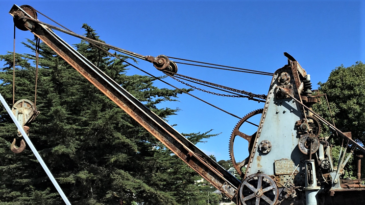
Older crane designs are manufactured today with improvements. Why? Because they still meet the requirements of the job. A perfect example of this staying-power is the lattice boom, wire rope luffing crane mounted on locomotives, trucks, and crawlers. These machines have been transmuted over the last 110 years, but essentials do the same work (Fig. 2).
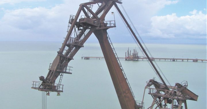
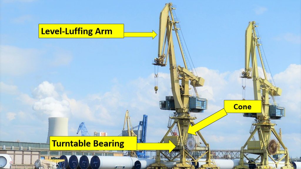
Another older design still being built in some parts of the world is the “level-luffing” port crane. The Indian “new” port crane involved in this accident is of an older design from the 1920s — a mechanical Level-Luffing duty cycle port loader/unloader. An example, located at a port in Trinidad (circa 1942), is shown in Fig. 3. The turntable is located lower to the portal and is supporting the revolving upper works. Modern designs improve two aspects of level-luffing cranes and over-all lowering of the crane’s center-of-gravity and high maintenance costs — a lot of moving parts.
INDIAN PORT ACCIDENT, 2020
This crane was delivered to the site two years ago for commissioning. At that time, it failed, and various deficiencies were issued, but the manufacturer, Anupam Crane of Mumbai, did not repair the problem. Anupam joint ventured with a Japanese firm to build the crane. Two years lapse without any repairs, and the owner contracted Greenfield Corp. to clear the deficiencies and commission the crane.
The operating advantage of “level-lulling” is to increase productivity when loading/unloading of bulk material at ports. Handle bulk-cargo calls for continuous 180 degrees rotation, increase/decrease of boom angle/radius, and the hoisting/lowering of a load, then opening/closing a clam bucket to deposit the material. The result is that when the boom went up, the rocker-beam hoist end lowers. The result is that the hoist load remained level with the earth. Synchronizing the boom and hoist drive motors for new cranes has eliminated the need for this rocker beam design with all its negatives and produces the same results.
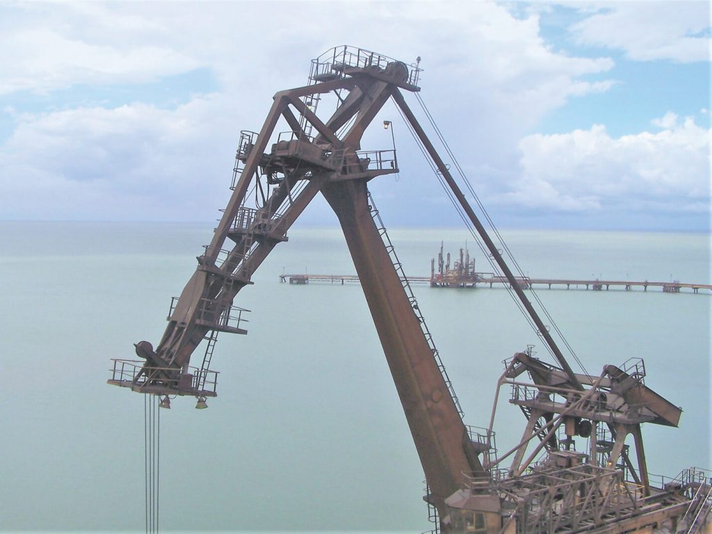
The turntable bearing support area failed, as evidence by the videos available on YouTube. All the mass of the load, crane upper works structure, and inertial moments concentrated at this rotating bearing located at the bottom of the gantry and overwhelmed its structure (Fig. 4).
What could have been different if we were the test directors? Oh yes, the inspector/surveyor has had a change in his job description, responsibilities, and title. Test directors know their primary duty at this point is to signal the movement of the crane, when overloaded, away from other equipment, and limit personal to those required for the testing within the area. Then this crane’s failure; there were twelve people on the crane. Why?
ORION SHIP CRANE ACCIDENT, 2020
This beautiful new Chinese 5,500-ton super heavy-lift offshore work ship is the Orion. Sort of a modern miracle of engineering, so though! The reported cause of this accident (I would think) sent the crane builder Liebherr’s management and engineers into shock. I would have to invent a whole new word to describe what they must have felt! Classic failure — load drops off-hook, boom recoils back over the crane (but rarely does the hook break, twice in my sixty years, and that was long ago.) This dramatic accident, caused by the lower “keeper” failure of a vendor’s hook. Was the hook tested before assembly? How would you build an 8,250-ton (150% of capacity) test fixture? Expensively.
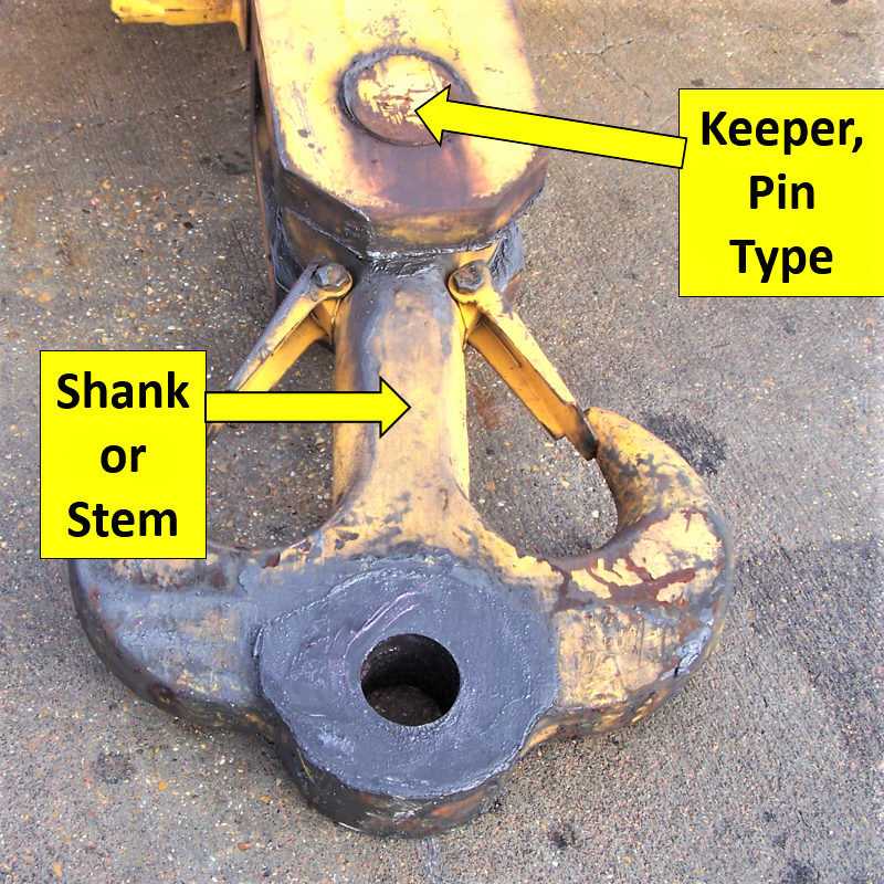
Most crane hooks are basically in two parts. The hook with its shank is one piece and the other a “keeper” of some design to secure the hook to the hoist block. Industries forge most hooks, but some are cast alloy steel, Fig. 5.
The hook that failed was of a new modern design made from four parts due to its massive size and capacity. It is an assembly of; a shank (stem), top keeper, which appears to be a pin and eye connection, a four-prong hook that slid on the shank, and a bottom keeper to hold the hook on the shank. It was this bottom keeper that failed, allowing the hook to slip off the shank, dropping the load. No inspector could have determined this manufacturing defect. This is the reason cranes are tested under controlled conditions.
SHIPS CRANE FAILURE
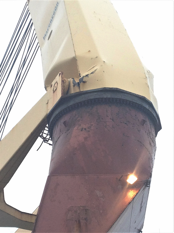
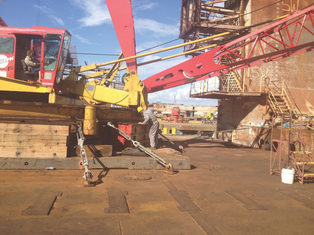
A 100-ton pedestal crane was due for its quadrennial inspection and load testing for maritime certification. When these cranes lift loads from the ship’s deck, then rotates to the dock and unload the cargo, the ship must remain level. This Indonesia flag ship leveling is accomplished by high-speed jet pumps that transfer ballast water from one side of the ship to the other to maintain a minimum “list.”
When picking up the test load, the jet pumps were not activated, causing the ship to list approximately 12 degrees, sideloading the crane and triggering the pedestal failure. The test load swung starboard approximately twenty-eight feet and hit the dock, no injures (Fig. 6).
In this case, outside occurrence beyond the control of the test director caused the crane to fail. Properly controlling the test area avoided personal injury.
RAIL FAILURE
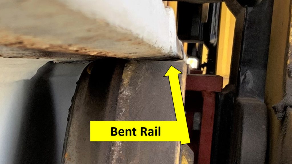
Here the crane surveyor performed (before being elevated to test director) his duty during the quadrennial inspection. Wheel contact area is reduced to one third, increasing wheel and bearing loading. He had visually located deformed rails. Some deforming was first noted and monitored during monthly inspections by the owner.
The rails are fabricated. A rectangular-shaped railhead welded to a top flange that is welded on a vertical web, which in turn is welded to the deck base plate and gusset supports welded. This deficiency was on a four-year-old Turkish crane. Cause — residual welding stress (per manufacture.) Fortunately, the rail was good enough to last as long as it did under the light service at this U.S. shipyard (Fig. 7). This is what we would have expected to find during the inspection — before testing.
CONCLUSIONS
The question first asked, how can accidents like these be prevented? Well, there is an interesting connection in all these accidents. The joint ventures between companies and nations to build or test the crane. The large hook that separated (China/Germany/Dutch), the crane turntable/bolts disconnection (India/Greenfield/Japan.) Then the ship’s pedestal collapse (Netherlands/Indonesia/USA), and the improper rail fabrication (Turkey/ITT/USA) during load testing. These types of collaborations are a trend in our industry.
The decisions made by managers of the joint ventures control the success or failure of these activities. They can be separated, 1. The defects were preventable only at the subassembly level, requires adequate quality control, 2. Standard commissioning procedures need to be followed, no shorts-cuts during inspections, and control personal access to the test area 3. Accidents like these start the blaming, and the hiding of the facts — sealed agreements — prevents informing the industry.
As these cranes become so gigantic and complex, I am concerned about Certifying Concealed defects, which will, from “time to time, rear their ugly heads.” Creating safety is done every day by how people work and communicate with each other — distance impedes. Everyone involved takes responsibility.
ABOUT THE AUTHOR
DENNIS J. O’ROURKE, CSP, is the Director of National Crane Services, Inc. He has over sixty years’ experience in the industrial, maritime, and construction fields working with heavy equipment and material handling devices. As a safety engineer, Mr. O’Rourke has developed and/or presented hundreds of safety-training programs for all representative elements of government and industry. (dennis@natlcrane.com)